Product Quality Improvement with Correct Moisture Measurement in Thermal Processes Using Electrolytic Hygrometers
By Jerri Jefferies,
Sales Engineer
MEECO, Inc.
Electrolytic hygrometers generally have been overlooked in the metallurgical processing of materials, despite being well suited for these applications. Indeed, electrolytic technology lends itself to use in heat treating, particularly vacuum heat treating. It combines the versatility and accuracy that is critical for optimum product yields. Moisture analysis at different phases of the heat treat process is crucial, as explained below. This coverage, along with the basic principle of operation and calibration verification techniques, form the topic for this article. It is excerpted from a paper presented at the ASM 14th Heat Treat Conference and Exposition in Indianapolis, Indiana, last March.
MOISTURE ANALYSIS IN VACUUM HEAT TREATING APPLICATIONS
Low oxygen and moisture residuals are essential to processing aircraft engine components made from nickel-based alloy materials, particularly those containing traces of titanium, niobium, tantalum or aluminum. These materials oxidize in the presence of even small concentrations of O2 and H2O. Many other metals processed in vacuum are cooled or quenched in inert gases, and must be as free as possible of residual oxygen or water to avoid contamination.[1]
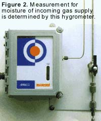 |
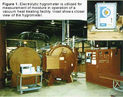
In a vacuum heat treating process, for example, use was made of an electrolytic moisture transmitter (see Figure 1).[2] Originally, the unit was obtained to verify the basic quality of gas from the supplier and to insure the integrity of the gas distribution system throughout the plant (see Figure 2). Its other uses were immediately apparent, however. |
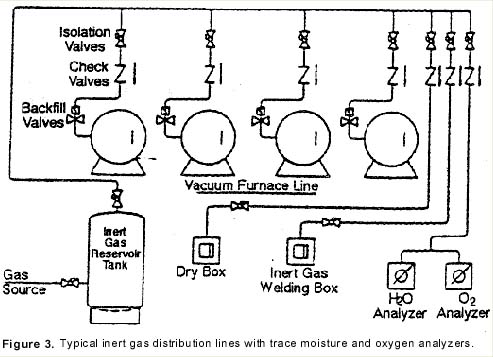
Figure 3 shows the suggested configuration for moisture analysis in a heat treat application.[1] Note that the moisture and oxygen analyzers are at the end of the line. They will detect any leaks and verify the integrity of the entire system.
Experience with Inert Gas Reservoir Tanks
Operating experience at a commercial heat treating plant[4] yields continuous O2 level reading of less than 1 ppm and less than 3 ppm H2O in nitrogen gas. In argon gas, purity levels run less than 0.5 ppm O2 and less than 1.5 ppm H2O.
Observed over a period of several years, gas leaks in piping joints, valve bonnets, and pressure regulators normally occur at start-up. Generally, once these are repaired, gas leaks do not develop. Good design practice requires all welded or brazed piping connections with a minimum of pipe thread joints.
Initial testing should start with standard soap bubble techniques. Final testing should entail a complete vacuum pump down to less than 10-2 torr and a Helium Mass Spectrometer[5] for testing of entire piping and reservoir tank directly back to the liquid gas source.
|
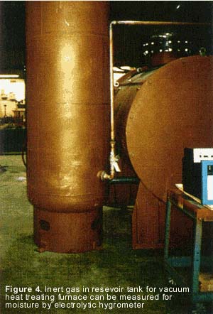
Prior to filling an inert gas reservoir tank (Figure 4), it must be fully evacuated to less than 10-2 torr using a suitable vacuum pump [6]. The reservoir tank should be filled with inert gas to operating pressure; then follow a blow down to atmospheric pressure and re-evacuation with the vacuum pump. This process should be completed three times, with at least eight hours of continuous vacuum pumping, to ensure complete clean up of residual air and water from the tank. Any evidence of condensation in the bottom area of the tank indicates water is present and may require flaming the bottom of the tank with a torch to evaporate any residual water. The reservoir tank may then be charged with gas, following final purge.
The electrolytic hygrometer can test the moisture content in gas reservoir tanks. By a continuous purge with nitrogen, the moisture content is checked periodically during the final drydown of the tank. While the oxygen content was reduced to low ppm range in one-to-two hours by the constant purge, it took considerably longer to evacuate the reservoir tank of high moisture concentrations to below ten ppm and may require several days to reach a low ppm level.[1] |
Vacuum Furnace Testing
Using an electrolytic hygrometer, leaks can be detected, and gas conditions can be verified in operation of a vacuum furnace heat treating facility (see Figure 1). Moisture intrusions can occur in the recirculation system. Problems, such as a leaking heat exchanger or atmospheric air leaks can be isolated quickly so that oxidation of the product will not occur during gas quenching operations.
The electrolytic hygrometer tests the purity of incoming gas to the entire operation. By mounting the electrolytic transmitter for continuous on-line analysis, leaks in the gas distribution system can be targeted before starting furnace operations.
Using a series of test valves to isolate various stages of the operation, one may check the incoming gas supply, (Valve A); the gas coming out of the reservoir tank, (Valve B), and finally, the quench gas quality before it enters the furnace for gas quenching (Valve C). (See Figure 5)
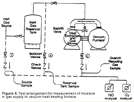
Moisture in gas purity levels at test positions A and B will normally run less than one ppm O2 and less than three ppm H2O as noted above. During gas quenching and sampling at test valve C, a positive pressure over 5 psig is required.
With limited testing of a new vacuum furnace, it was noted that the initial O2 and moisture indications were of the order of the supply gas. However, with continued gas recirculation blower operation, the O2 remained in the low ppm range and the moisture levels appeared to rise beginning in the low ppm range to over 20 ppm in operating for a period of one hour. The furnace was verified not to have any water or atmospheric air leaks and this anomaly is believed to be related to residual moisture from hot zone or other components of the furnace, similar to a vacuum “rate of rise” consideration.[1] Since the instrument is a 2-wire transmitter, one may utilize an existing power supply, computer, chart recorder, alarm system, or panel meter, thus minimizing overall instrumentation needs. This transmitter can even be installed directly into a vacuum furnace, utilizing its existing instrumentation.
ELECTROLYTIC PRINCIPLE
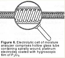
Electrolytic moisture analyzers employ an electrolytic cell for moisture measurement. The cell consists of a hollow glass tube with two platinum electrodes spirally wound around the inside wall (see Figure 6). The electrodes are covered with a thin, hygroscopic film of phosphoric pentoxide (P2O5). The sample gas is passed through the glass tube and the P2O5 film attracts and absorbs all of the moisture.
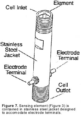
This assembly, called the sensing element, is surrounded by a protective metal body (see Figure 7). This complete assembly is plumbed into the analyzer’s flow system.
|
|
Mode of Operation
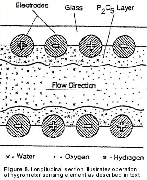
| In operation, the sample gas enters the cell at a known flow rate, and the film absorbs all the moisture molecules present in that gas flow. A DC voltage of approximately 24 volts is applied across the electrode terminals. This causes moisture to electrolyze in the film (see Figure 8). Each electrolyzed water molecule displaces two electrons from the anode to the cathode. The electrolysis current, which is measured in microamps, gives the electrical charge, or Coulombs, displaced per second. Consequently, since the elementary charge of an electron is known, one can determine by current measurement the rate at which water molecules enter the cell. This, combined with the known total flow rate, of the gas through the cell, gives a known concentration of moisture in the sample gas. |
|
For example, at a flow rate of 100 standard cc’s per minute, 1 part per million (ppm) by volume of moisture corresponds with a current of 13.2 microamps. Faraday’s Law, which relates chemistry to electricity, provides that 1 water molecule equals 2 electrons, or 100 sccm of 1 part per million H2O equals 13.2 microamps, 2 parts per million will equal 26.4 microamps, etc.
Thus, the use of an electrolytic hygrometer with a known flow rate of 100 cc per minute, with a positive pressure of 5 psig and above, will accurately measure moisture.
Verification of Calibration Techniques
Since the electrolytic hygrometers are based on Faraday’s Law, which is an absolute principle of physics, calibration is not actually necessary. However, to accommodate the interests and special requirements of many users, several techniques for verification of calibration will follow.
There are several different ways to verify the proper operation and calibration of an electrolytic moisture analyzer. A “Delta Flow” test can be used both to verify that the analyzer is functioning properly and to provide a linear output with changes in moisture content. Since the signal output of the electrolytic hygrometer is based on Faraday’s Law, and is therefore dependent on flow rate, by cutting the flow rate in half to 30 cc’s, the amount of moisture entering the cell also is reduced by half. Therefore, the moisture reading should drop in half. Because the electrolytic cell gives a linear reading, this test can be done on a day-to-day or week-to-week basis.
There are other methods to verify calibration in-house. One method is to compare the analyzer reading to the output of a moisture generator with a known or certified output. Cylinders of inert gas with a certified moisture content can be purchased and used to verify analyzer calibration. Precision dewpoint sources can also be used to verify calibration. A future article is planned outlining this technology.
Because N.I.S.T. traceability is becoming increasingly important, especially in the aerospace industry, the company has developed a program to test components against N.I.S.T. standards to provide calibration certification. Alternately, one may send the instrument to an independent testing lab or N.I.S.T. for certification.
CONCLUSION
Since their development in the early 1950s, electrolytic moisture analyzers have been widely used in relation to natural gas pipelines. Semiconductor manufacturers, industrial gas producers, petrochemical and plastics manufacturers consider electrolytic moisture analyzers as standard equipment for moisture measurement in various processes. The examples outlined in this article also show the potential for quality improvement by moisture measurement using electrolytic hygrometers in heat treating applications.
References
- Test data courtesy of W. R. Jones, Vacuum Furnace Systems, Souderton, PA.
- MEECO Model AccupointTM moisture transmitter, Warrington, PA.
- MEECO Model OxychekTM oxygen analyzer, Warrington, PA or Teledyne, or equal.
- Solar Atmospheres, Souderton, PA.
- Varian Model 924, Lexington, MA, or equal.
- Welch Model 1397, Skokie, IL or equal.
Reprinted from INDUSTRIAL HEATING, October 1993
