By Jacques Mettes
Third International Symposium on Humidity & Moisture, 1998
ABSTRACT
In many gas applications as, for examples, when the sample is small, toxic, reactive, expensive or when monitoring the breakthrough of certain purifiers, a fast, reliable indication of moisture exceeding a maximum allowable level is preferable to the relatively slow determination of the exact level. Hygrometers are inherently slow to register a large change, thus a method is presented that adds small, controlled amounts of moisture to keep the concentration in the sample gas cycling within a narrow band, just above the desired alarm level In this way, one can very rapidly detect when the sample gas concentration exceeds the alarm level. Moreover, every moisture addition allows one to check the speed of response of the hygrometer.
KEYWORDS: Electrolytic, Low-level, Parts-per-billion.
INTRODUCTION
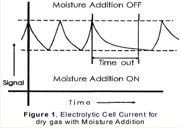
Parts-per-billion moisture analysis is conducted routinely on gases used in semiconductor manufacturing, where the gas quality is critical to the process yield [1]. Moisture measurements can be performed with the coulometric method, invented by Keidel [2], which is an absolute technique [3], reliant solely upon physical principles and which does not require calibration against a moisture standard. Faraday’s law relates a moisture concentration to the size of an electrical current and that of a gas flow, which are both easy to measure and calibrate. In many gas applications, a fast, reliable indication of moisture exceeding a maximum allowable level is preferable to the relatively slow determination of the exact level. For one, it is impractical to spend a long time measuring individual cylinders when the gas is toxic, reactive, expensive or supplied in a small quantity. For another, when it comes to the detection of moisture breakthrough in certain purifiers, the certainty and speed of detection are more important than the precise knowledge of the concentration below the breakthrough level. Figure 1 By contrast, hygrometers are inherently slow in registering a large change. A recently introduced electrolytic hygrometer [4] applies controlled moisture additions to keep the moisture concentration of the sample gas in the hygrometer cycling within a narrow band just above the desired alarm level. In this way, one can quickly detect when the sample gas concentration exceeds the alarm level. Moreover, every time small controlled amounts of moisture are added to keep the concentration within the band, the responsiveness of the hygrometer can be checked.
INSTRUMENT DESCRIPTION, MEECO SPRITETM
The additions are conducted on a simple on/off basis controlled by the hygrometer signal. Moisture is added when the hygrometer reads below a band, see Figure 1, and stops the additions when the readings are above the band. As long as the moisture level in the sample gas is well below the band, a stable, cyclic pattern in the hygrometer’s response signal is created, consisting of a rising and a downward slope. When the moisture level in the sample gas increases, the drydown slopes lengthen. When the moisture level is close to or exceeds the lower limit of the band, a time-out alarm is triggered. In practice, cycle times of three minutes are achieved on single digit ppb “dry” gas, while the alarm level can be set as low as 50 ppb with a time-out set at 15 minutes. Additionally, the steepness and consistency of the rising slopes help to monitor the responsiveness of the instrument on-line. To achieve this, one issues another time-out alarm when the wetting part of the cycle exceeds a maximum allowable time.Figure 2 As an inexaustibie moisture source, atmospheric moisture generates the additions. Figure 2 shows the flow schematics of the instrument. Before the incoming gas enters a needle valve, a small stream of gas is split off to flow through a piece of plastic tubing. Atmospheric moisture permeates through the wall of this tubing and is added to the gas stream, which is then either merged back into the main flow downstream of the needle valve (the moisture addition “on” position), or discarded (the moisture addition “off” position).
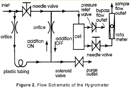
The direction of gas flow in the tube connecting the main stream downstream of the regulator to the plastic tubing is opposite in the two positions, where it consists of unwetted, main stream gas that merges with the wetted stream in the moisture “off” situation. The moisture addition is controlled by opening or closing a solenoid valve that allows or blocks the discard of gas. Flow restricting orifices control the size of the flows and check valves prevent moisture from reaching the cell in the absence of any flow, such as during shipment.
After the moisture addition, the mainstream of gas enters the housing of the electrolytic cell, where part of the flow passes through the cell itself, hereinafter called the sample flow. The remainder of the flow splits off at the element’s entrance to form a so-called bypass flow, designed to create a large throughput of gas in the instrument. The fixed pressure drop over a pressure relief valve upstream of the bypass outlet will also be present over the needle valve, thus controlling the sample flowrate.
REFERENCES
- Dance DL, Markle RJ, and Burghard RW, “Estimating the Costs of Contamination,” in Microcontamination 92 Conference Proceedings, Santa Monica, CA, Canon Communications, pp 143-152, 1992.
- Smith M, and Mitchell J Jr., “Coulometric Hygrornetry,” in Aquametry (part 2), 2nd ed, New York, Wiley and Sons, chap 3, 1984.
- Hulanicki A, “Absolute Methods in Analytical Chemistry,” Pure & Appf. Chem., Vol. 67, No. 11, pp. 1905-1911, 1995.
- Ma C, Shadman F, Mettes J, Silverman L, “Evaluating the trace-moisture measurement capability of coulemetric hygrometry,” Micro 1995, Canon Communications, Inc.
